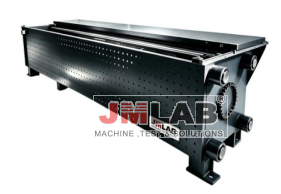
Product Highlights
1.Testing speed is continuously adjustable from 1-90 mm/min, with a maximum piston speed of 250 mm/min, meeting various standard testing speed requirements for tensile testing.
2.Effective testing space is customizable from 800-3000 mm, and effective testing length is 1600-3000 mm, easily accommodating various bolt lengths and meeting diverse testing needs.
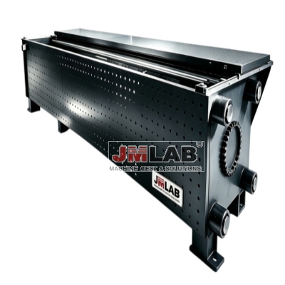
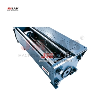
3.Horizontal four-column hydraulic single-pull structure design - the hydraulic cylinder retracts and pulls the front beam via a load sensor to achieve sample tensile testing. It features high rigidity, excellent alignment, and long-term stability.
4.Tensile testing machine for bolts up to M90, with a maximum static test force of up to 5000 kN - a custom-designed model specifically for load-bearing and static load testing of large-diameter bolts from M24 to M90 - ideal for wind power, bridge, and steel structure applications.
5.Test force indication accuracy reaches ±1% of the indicated value within the range of 2%-100%. Equipped with a fully digital hydraulic servo controller for closed-loop control, ensuring accurate and reliable test data.
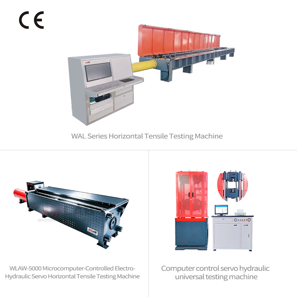
6.CE certified, ensuring compliance with international standards.
Produkteinführung
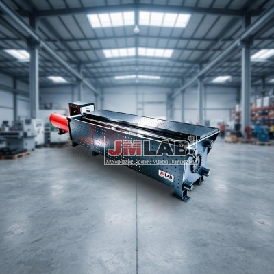
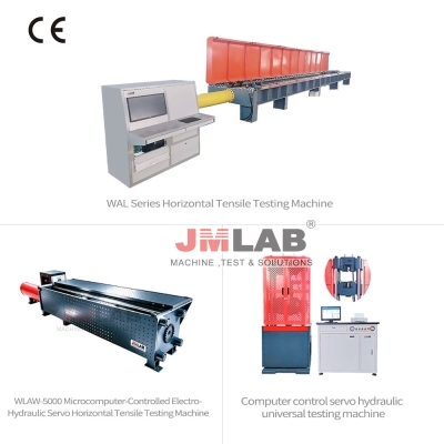
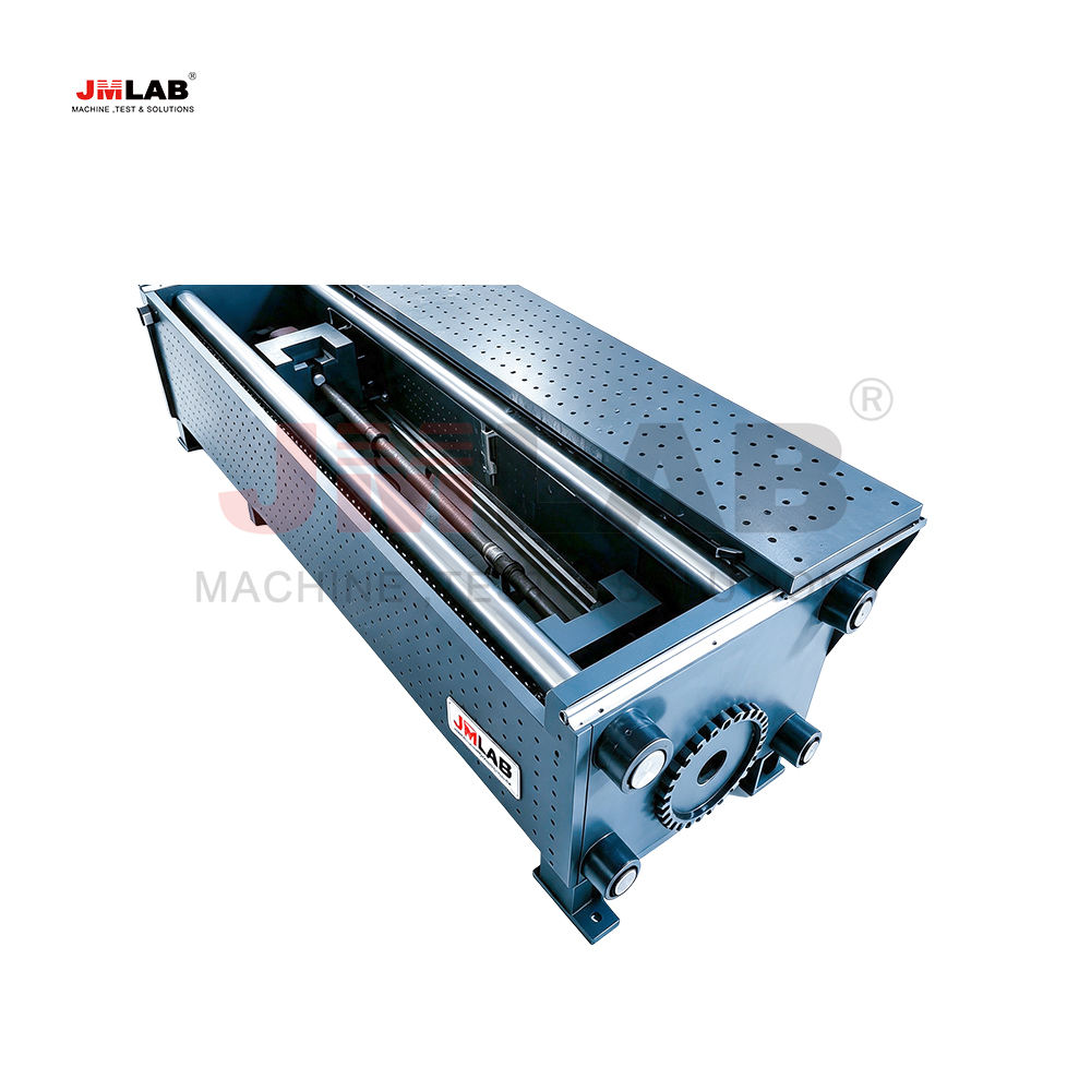
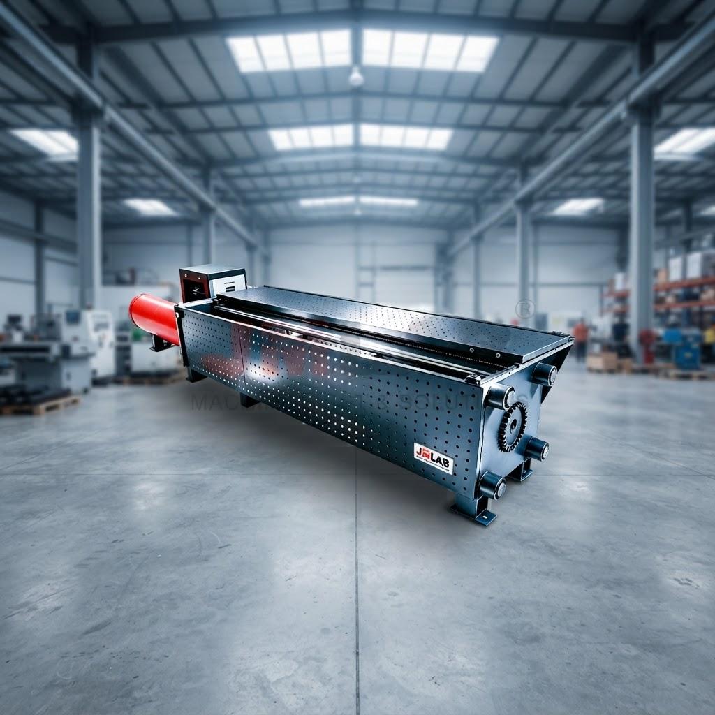
The WLAW-5000 microcomputer-controlled electro-hydraulic servo horizontal tensile testing machine is a structural testing device specifically developed for research institutions, testing units, and universities. It is primarily used for testing the load-bearing and static load performance of bolts.
This machine is mainly used for testing the load-bearing capacity and static load performance of bolts.
This testing machine consists of a loading frame main unit, a 5000kN horizontal loading servo cylinder, an electro-hydraulic servo oil source system with a rated flow rate of 16.5+50L/min, an electro-hydraulic servo controller capable of closed-loop control, and software.
The device is designed as a horizontal four-column hydraulic cylinder single-pull structure. When the hydraulic cylinder retracts, the forward moving beam is pulled by a load sensor to achieve sample tension.
It meets the general technical requirements of GB/T2611 testing machine.
Eigenschaften
1、Main unit rack
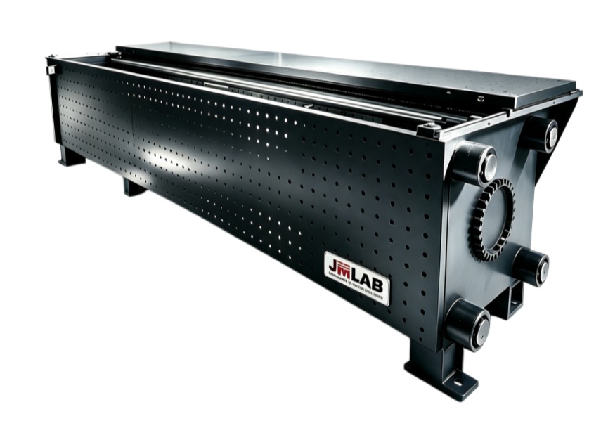
It adopts a horizontal structure and mainly consists of a main hydraulic cylinder mounting beam (front beam), four columns, a movable clamping body, a rear fixed clamping body, a rear beam, a protective cover, and a lower support.
Main frame loading mechanism
The main frame is formed after the main cylinder mounting beam, four columns, and rear beam are installed.
The front moving clamp is connected to the hydraulic cylinder via a sensor, while the rear clamp is fixed to the rear beam.
The height of the hydraulic cylinder loading center shall not be less than 0.5 meters;
Four pillars: manufactured by precision machining after aging treatment.
Front beam and rear beam. Rear steel plate structure, made of 45# steel, manufactured with precision machining after aging treatment.
The front beam is connected to the hydraulic cylinder;
The total width is approximately 1200mm.
Front clamp moving device
The guide moves the lower column, facilitating sample installation.
The maximum adjustable effective test space is not less than 0.8 meters to 3 meters.
Meets the requirements for bolt testing from 1.6 meters to 3 meters in length.
Test fixtures
The front and rear clamps are designed with a wedge-type clamping structure, meeting the testing requirements for M24-M72 bolts. It comes equipped with 13 types of breaking fixtures (26 pieces), 13 types of nut-holding mandrels (13 pieces), and 13 types of spacers (26 pieces).
other
It is sealed on all four sides and has a sliding protective cover on top.
The layout of related wires, cables, hoses, etc. is reasonable and the protective measures are complete.
The main unit automatically stops when the sample breaks. It can also be designed to stop at a specified experimental value.
Key technical parameters of the host loading framework
(1) Maximum test force: 5000kN;
(2) The test space is infinitely adjustable; the hydraulic cylinder is infinitely adjustable.
(3) Maximum stroke of hydraulic cylinder: 2200mm;
(4) Effective test length: 1600-3000mm
(5) Effective test width: 420mm
(6) External dimensions: 7600*1200*900 mm (L*W*H)
(7) Weight: Main unit approximately 8 tons
2. Servo cylinder section
The servo cylinder adopts a single-rod double-acting structure, uses German Bosch vane seals and oil-free lubricated bearing guide sleeves, and a wire-type displacement sensor is installed on the cylinder.
Key technical specifications of the servo cylinder
(1) Maximum test force: 5000kN;
(2) Maximum stroke: 2200mm;
(3) Indication error, within the range of 2% to 100% FS, shall not exceed ±1% of the indicated value.
(4) A high-precision load sensor is used to measure the force.
(5) Displacement resolution: 0.01 mm;
(6) Displacement measurement accuracy: not less than ±1%
(7) Maximum piston movement speed: 250 mm/min;
(8) Test speed: 1 mm/min - 90 mm/min
(9) Overload protection: Overload protection exceeding 105% FS (without deformation or mechanical damage)
(10) High strength, designed according to test requirements:
(11) Piston diameter: Material 45#, φ500;
(12) Hydraulic cylinder material: 45# steel, with honed inner bore;
(13) Piston rod diameter: 200mm, material 40Cr, tempered HB220-250, high-frequency quenching treatment on the outer circle;
(14) The maximum withstand pressure is designed to be 31.5 MPa.
(15) When the system working pressure is 30.5 MPa, the maximum test force shall not be less than 5000 kN;
(16) The servo cylinder adopts a single-rod, double-acting structure.
(17) The piston rod support breaks with traditional design, adopting a multi-stage non-metallic flexible support combined with a graphite copper sleeve, which greatly reduces starting friction and has a certain lateral load-bearing capacity. It has excellent wear resistance and superior low-speed performance, and its testing performance is greatly improved compared with traditional designs.
(18) All sealing elements of the servo cylinder are imported high-speed sealing elements specifically designed for servo cylinders. They are resistant to high temperatures and wear, and feature high-speed non-sintering self-lubrication, which greatly improves the sealing performance, as shown in Figure 3.
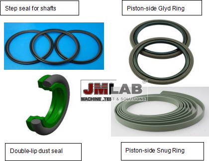
Figure 3
(19) The end cap supporting the piston rod employs a structure of step seal + wear ring + step seal + dust seal + graphite copper sleeve. It achieves three levels of sealing through two stages of step seals and one stage of dust seal. The first stage seal, closest to the oil chamber, is a high-pressure seal, followed by a low-pressure seal. After these two stages of sealing, a small amount of low-pressure oil will still remain on the piston rod surface. The third stage seal is a double-lip dust seal; the inward lip tightly adheres to the piston rod, providing a low-pressure seal, while the outward lip provides dust protection. The diagram below illustrates the working principle of the step seal + wear ring + dust seal.
(20) The main function of wear-resistant rings (support rings, guide rings, graphite copper sleeves, etc.) is to provide guidance and support for the piston and piston rod, absorb radial loads, and prevent metal-to-metal contact between moving parts of the hydraulic cylinder. They feature high load-bearing capacity, good wear resistance, good friction characteristics, vibration damping, and low maintenance costs. The selection of materials is crucial depending on the hydraulic cylinder's operating conditions (this is proprietary technology of our company and will not be discussed further).
(21)The piston rod material undergoes quenching and tempering treatment and is plated with hard chrome to increase surface hardness. At the same time, it is ultra-precision ground to create a mirror finish on the piston rod surface, which is an important condition to ensure that the piston rod does not leak.
(22) The servo cylinder is equipped with a load sensor specifically designed for testing machines at its front end.
(23) The displacement sensor is a wire-type displacement sensor, which is highly accurate and easy to use.
(24) Servo cylinder installation method: The front cover flange is installed at the center of the main unit's frame beam, and the rear end is supported on the foundation by a bracket.
3. Hydraulic servo pump station
(1) <Total flow rate: 16.5 + 50 L/min;
(2) The 16.5 L/min pressure of 31.5 MPa was used for tensile and load holding tests;
(3) The pressure of 50 L/min at 5 MPa is used for rapid adjustment of the test space.
(4) Total power 5.5 + 11KW, motor 380V, AC
(5) The 11KW servo motor, combined with a high-pressure pump, is used for tensile and load-bearing tests.
(6) The 5.5KW servo motor, combined with a high-pressure pump, is used to quickly adjust the test space.
(7) Fuel tank capacity 1000L
(8) The high-pressure oil pump is a Texas high-pressure pump with a maximum pressure resistance of 40MP and excellent durability.
(9) The oil pump motor unit is equipped with a shock absorption device to reduce vibration and noise;
(10) It features temperature measurement, high-pressure oil filtration, oil suction filtration, air filtration, oil level display, system pressure display, etc.
4. Control System and Control Software
The microcomputer-controlled electro-hydraulic servo measurement and control system consists of our company's independently developed TMC controller and EVOTest measurement and control software. The system collects high-precision force sensors, displacement sensors and other sensors to realize closed-loop control of cylinder load, displacement and other channels, and can realize switching of control modes. It features high control acquisition accuracy and high stability.
ØControl system performance characteristics:
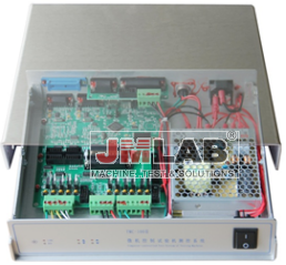
This controller uses a 32-bit high-speed ARM chip as the main control chip, which has high computing speed and data processing capabilities. It can realize the entire control process from data acquisition, PID calculation, network communication to output control in a short time, thereby achieving precise closed-loop control of the testing machine. The controller supports remote firmware upgrades to realize more customized functions.
1. Input Channel:
1) Three high-precision 24-bit A/D conversion channels, standard sampling frequency of 50Hz (customizable from 1-1000Hz), effective resolution up to 1/500000, digitally adjustable gain, and multi-point correction for each sensor;
2) Three orthogonal encoded digital input channels: one channel uses a 10M/Bit optocoupler input for differential wire encoder or servo motor encoder acquisition, and the other two channels are used for large deformation interfaces.
3) It has 8 digital input ports, which can be configured for functions such as limit switches and emergency stops, and can be paired with a dedicated hand control box to achieve more external functions.
2. Output Channel:
1) One SWP output, 0-1MHz, is used for servo motor speed control. It can be configured as a dual-channel output to control two motors simultaneously.
2) 8-channel DO output, 24V, 1A output, directly drive relays or solenoid valves.
3. Network communication:
1) USB 2.0: High-speed communication with computers and laptops, industrial-grade anti-interference design, and driver support for any Windows operating system;
2) WIFI: 802.11 b/g/n, can be directly connected to Windows 10 tablets;
3) Industrial RS485 interface: supports MODBUS and HMI interconnection.
4. Data saving: The controller will automatically save the measurement and control parameters that have been debugged, and the debugged measurement and control parameters will not be lost even if the user changes the computer at will.
5. Independent controller, supports USB communication, and can be connected to various computers such as laptops and tablets.
6. The controller automatically saves the measurement and control parameters, and the computer can be replaced at any time without recalibrating the parameters.
7. The software has corresponding tension selection modules for different bolt sizes and models. To tension a bolt, the operator simply selects the appropriate tension direction and begins tensioning. Once the set tension load is reached, the equipment automatically stops, awaiting the next tensioning attempt. It is not necessary to break the sample.
Ø Main features of the measurement and control software:
l Experiment main interface
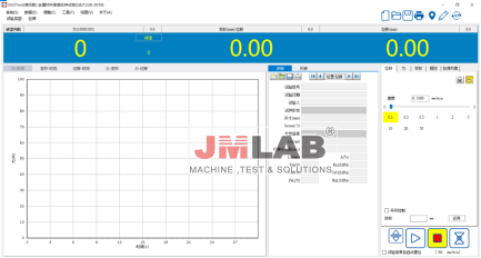
This measurement and control software features a beautiful interface, powerful functions, and easy operation. It fully supports multilingual switching under operating systems such as Windows 10.
1、 This measurement and control software records and dynamically displays test curves in real time, including force-time, displacement-time, force-deformation, force-displacement, and stress-strain curves. It supports multiple graph displays and allows users to switch between them at any time.
2、 he mechanical properties of the test material are analyzed and calculated using a human-computer interaction method. At the end of the test, the elastic modulus, yield strength, non-proportional elongation stress, etc. can be automatically calculated (the data analyzed will be different depending on the test method). Based on the automatic analysis, the analysis results can also be manually corrected to improve the accuracy of the analysis.
3、 It uses a standard database to manage experimental data, automatically saves experimental data and curves, and provides a network data interface;
4、 This measurement and control software provides users with a variety of report printing interfaces and report printing templates. Users can also edit and print reports in the form of EXCEL spreadsheets. It also supports batch printing of reports.
5、 This measurement and control software can be set to protect against over-range test forces, providing users with a safe testing environment.
This measurement and control software adopts an open test standard configuration mode. The standard software includes dozens of test standards such as GB/T228.1-2010 and GB/T1040-2008, and users can also easily add various test standards.
Technische Merkmale
◎Maximum static test force: 5000kN;
◎Test force indication accuracy: Within the range of 2%-100%, the accuracy reaches ±1% of the indicated value;
◎Maximum stroke of hydraulic cylinder: 2200mm;
◎Displacement resolution: 0.01mm;
◎Effective test space: 800-3000mm;
◎ Effective test length: 1600-3000mm;
◎ Effective test width: 420mm;
◎Maximum piston movement speed: 250mm/min;
◎ Test speed: 1mm/min-90mm/min
◎Overload protection: Overload protection exceeding 105%FS (no deformation, no mechanical damage);
◎Control system: Fully digital hydraulic servo controller;
◎Pump station: 31.5MPa, 16.5L/min, servo motor 11kW, three-phase, 380V;
5MPa, 50L/min, 5.5kW three-phase asynchronous motor, three-phase, 380V
◎Accessories: The front and rear clamps are designed with a wedge-type clamping structure, meeting the testing requirements for M24-M72 bolts. It comes equipped with 13 types of breaking tools (26 pieces), 13 types of nut retaining mandrels (13 pieces), and 13 types of spacers (26 pieces ).
Zufälliges Zubehör
Serial Number | Unit Name | Specifications and Models | quantity | Place of origin/manufacturing | Remark |
1 | Main unit rack |
| 1 | JMLAB | Includes crossbeam movement locking device, etc. |
2 | Servo cylinder | 5000kN | 1 | JMLAB | Single-acting rod |
3 | Force sensor | 5000kN | 1 | Bengbu Dayang |
|
4 | Displacement sensor | 2500mm | 1 | Kono |
|
5 | High pressure pump | 16.5L | 1 | Texas |
|
6 | Servo motor | 11KW | 1 | Weichuang |
|
7 | hydraulic hose |
|
|
| several |
8 | control system |
| 1 | JMLAB |
|
9 | Software System |
| 2 | JMLAB |
|
10 | computer | brand | 1 | Lenovo | 21.5-inch monitor |
11 | printer | A4 | 1 | Lenovo | 2205 |
12 | Protective covers and other supporting devices |
| 1 | JMLAB |
|
13 | Accessories, related mechanical parts, toolboxes, etc. |
| 1 | JMLAB |
|
14 | Wire and cable connectors |
| 1 | JMLAB |
|
15 | control cabinet | The hydraulic station and control cabinet are separate. | 1 | JMLAB | Individual control panel |
Safety protection measures:
Mechanical protection measures
1. Hydraulic cylinder limit protection
2. Hydraulic overload overflow protection
3. Test force overload protection
4. Automatic shutdown protection during test breakage
5. Automatic shutdown protection upon test completion
6. Phase sequence protection
7. Overcurrent protection

WAL-3000D Elektrohydraulischer Servo Horizo. ..
Mehr
Ankerkette Formung Zugprüfung mac. ..
Mehr
Kontinuierliche Ring Zugprüfmaschine
Mehr
Sicherheitsgurt und Sperrspannungsprüfung mac. ..
Mehr
JINAN JMLAB INSTRUMENT CO., LTD. spezialisiert auf R& D, Produktion, OEM von Prüfgeräten. Es ist seit mehr als zehn Jahren mit Metall- und Nichtmetallprüfungen beschäftigt und ist auch in verschiedenen nicht-Standard-Instrumenten kompetent. Produktion, Forschung und Entwicklung, Upgrade und Transformation automatisierter Instrumente usw. Seit der Gründung des Unternehmens haben die Produkte hohes Lob von inländischen und ausländischen Kunden gewonnen. Die Ausrüstung entspricht ASTM, JIS, ISO, IEC, UL, GB und anderen relevanten Prüfstandards.